
Are you tired as well, that seemingly the entire CAD landscape consists of extortionary licensing models that lure you into learning their tool for free and then slamming you with a massive subscription fee as soon as you’re hooked and start using it more? Or software that regularly removes features that you’ve grown to love? Well, worry no more, because there is an alternative, actually more than one, but for this video, I wanted to take another look at FreeCAD, a free and open-source, fully-featured CAD tool that is a perfect replacement for anything that Fusion360, Solidworks, Onshape, NX, Autocad, etc can do.
At least that’s what I would have liked to say about FreeCAD, but while there is a fantastic tool at its core in there somewhere, the software still leaves many of the challenges unsolved that tend to plague independently developed open-source tools. I hope I’ll be able to provide some input from a user’s perspective because I really want there to be a good open-source option, and I’ll also try to provide you with a perspective on whether FreeCAD might after all be the right tool for you already.
First of all, again, I have no intent on just bashing on FreeCAD, I think that simply wouldn’t be fair to a project that has barely any funding, is giving you their work for absolutely free, and also manages to deliver as complex of a tool as it does.
Still, I hope I’ll be able to provide some constructive feedback that perhaps explains why I can’t seem to have a good time every time I try to really get into and understand FreeCAD. I think this is my third time now that I’ll spend a dozen hours or so over the course of a couple of days, genuinely trying to use FreeCAD to create something, but every time, I barely manage to wrap my head around how the tool works and wants to be worked, I get frustrated, and ultimately go back to using Fusion360.
And I’ve used plenty of CAD tools before – from Catia v4 and v5, Solidworks, Inventor, Onshape, Fusion, I’ve used Tebis for CAM prep at a job, and I think I’ve even tried SolidEdge once, but those all eventually clicked for me. Why do I bring all those up? Well, first of all, I guess that legitimizes me as “not a total CAD noob”, but also because I think that helps me sort of put into context how the FreeCAD experience stacks up.
But, ok, what is FreeCAD? In their own words, it’s “your own 3D parametric modeler”, meaning, like Fusion, Onshape, Solidworks, that the 3D modeling process with it revolves around inputting your design constraints into FreeCAD in the form of sketches and features that, one after the other, describe and build up your model, and in the end, the CAD tool will try to give you a part that fits within those constraints – or parameters that you gave it. If you built your part well, you’ll even be able to go back to some of the earlier features, for example, change a dimension and your CAD tool will give you an updated part that solves for that new dimension.
That’s in contrast to direct modeling, which is for example the classic workflow for something like Blender, where you always build on top of the geometry you have at that very point and you can never go “back in time” to change a parameter and have the software rebuild everything after that to match. With direct modeling, there’s no going back. Except for the undo button.
But FreeCAD doesn’t just do parametric 3D CAD – it also does architectural CAD, 2D CAD, 3D simulation, analysis, mesh manipulation, OpenSCAD modeling, CNC programming, point cloud manipulation, rendering, reverse engineering, robot kinematics, spreadsheets, surface modeling, and web browsing.
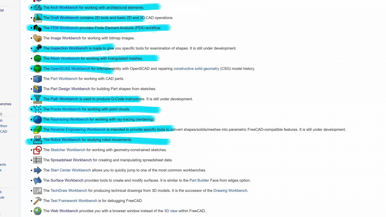
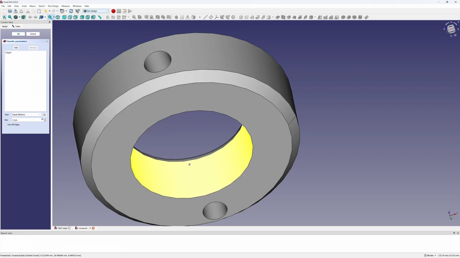
If that’s a little overwhelming, I feel you, but if you’re creating parts for 3D printing, basically, you’ll spend all your time in the “Part”, “Part Design”, and “Sketcher” workbench, and the basic workflow is the same as in any other parametric CAD tool. You start with a typically two-dimensional sketch, then create a 3D feature from that, next sketch, next feature, and so on, you’ve got your non-sketch tools for example for hollowing out bodies and creating a shell, you can add fillets and chamfers, and that part of FreeCAD actually works pretty well.
There are some limitations to how exactly you can design your parts, which stem from the way that the logic inside the geometry engine behind FreeCAD works, for example, you can’t completely sever two sections of a body, they always have to stay connected somehow, but generally, they’re not limitations you couldn’t work around. It’s not going to prevent you from designing a part, you might just have to approach it a bit differently.
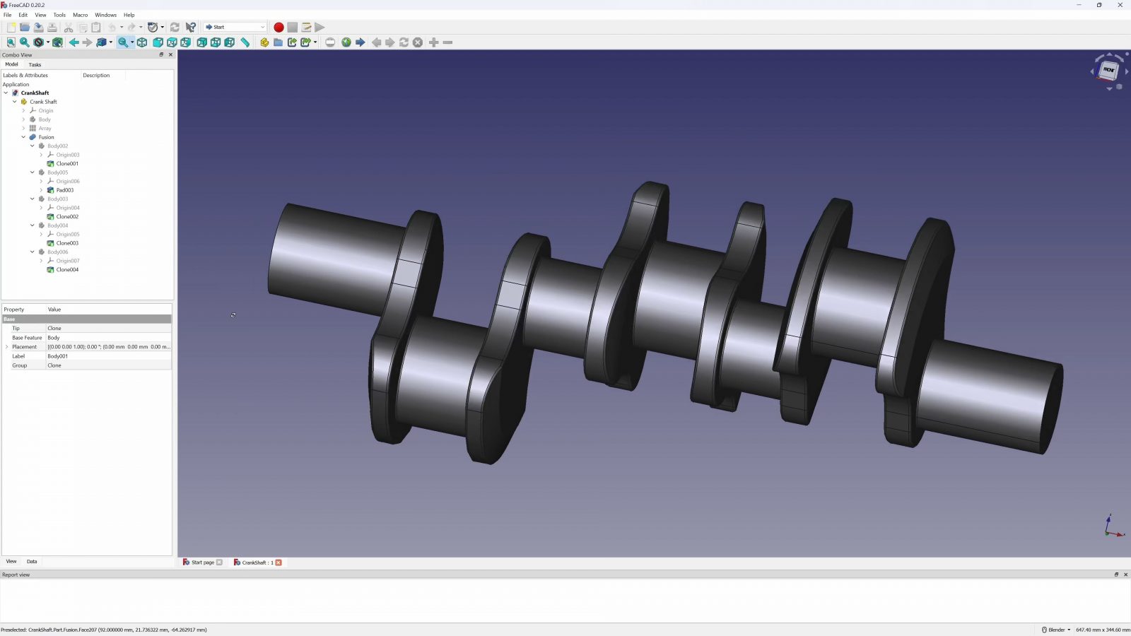
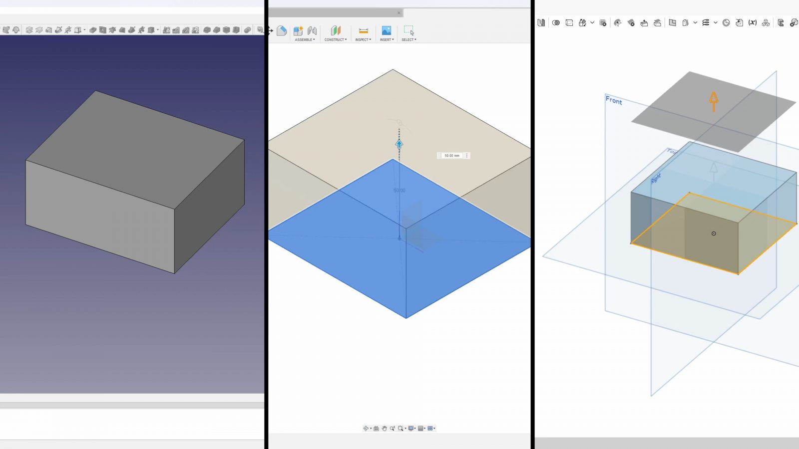
But of course, FreeCAD’s ambitions are quite a bit larger than just chucking together parts from basic extrudes, so I thought as a simple experiment, I’d try to recreate this part that I had made in Fusion360 just a couple of days ago – the initial design, including figuring out how to best design it, took me maybe an hour there, plus a couple of iterations to get the fit perfect, so I already knew the exact features and dimensions that I’d need to recreate it in FreeCAD.

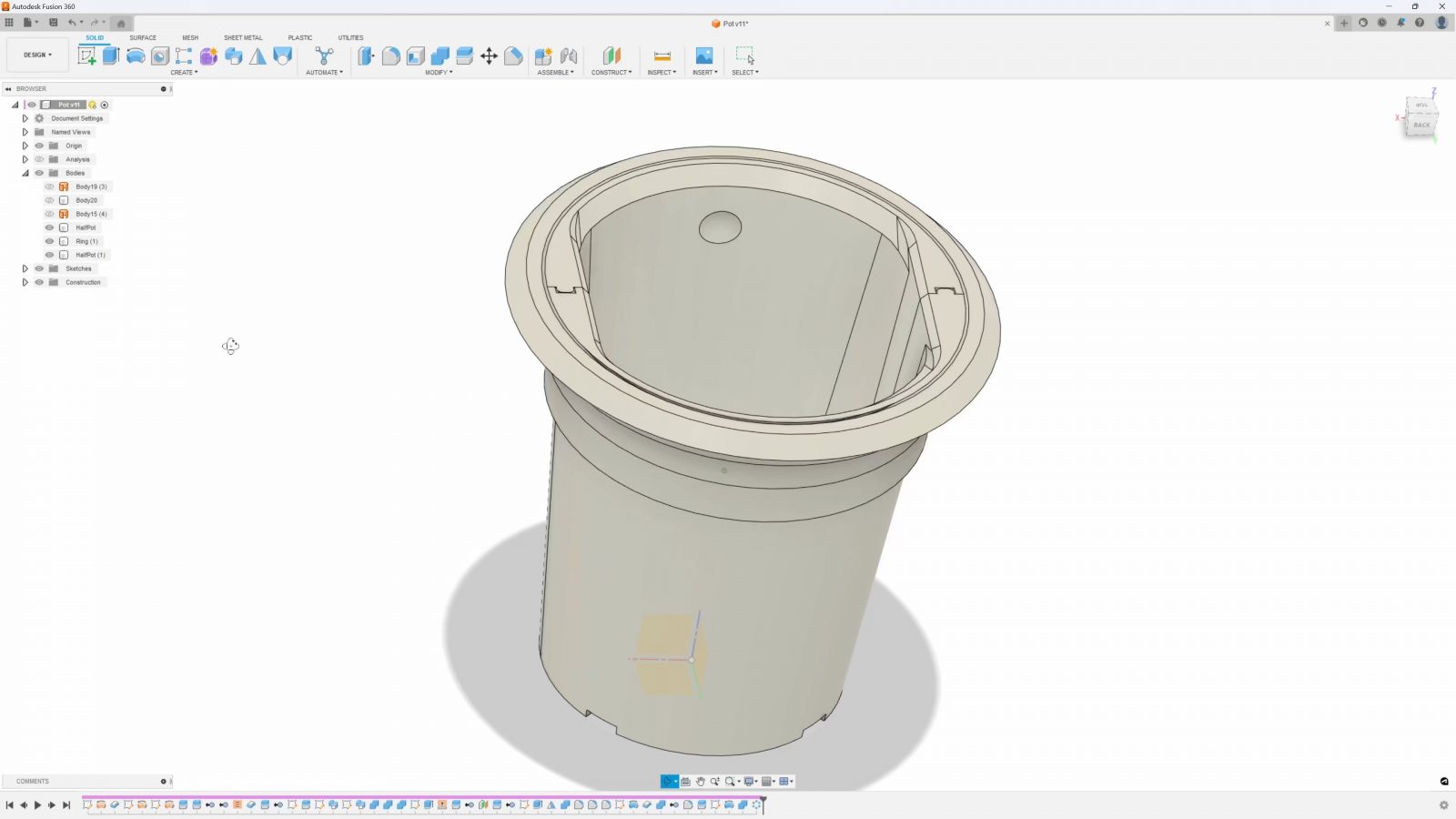
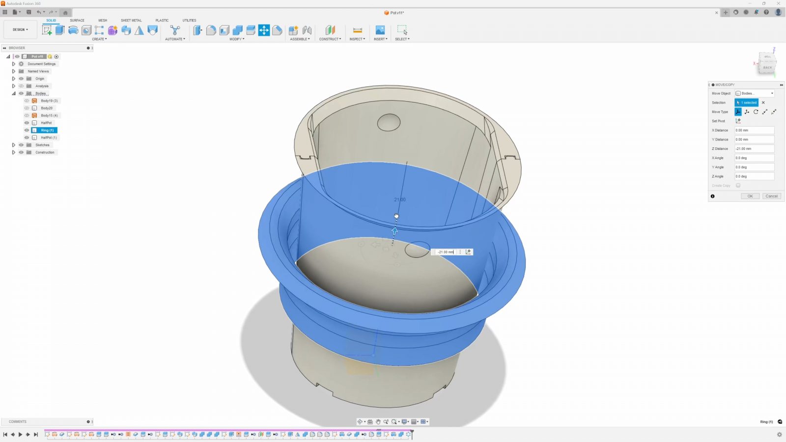
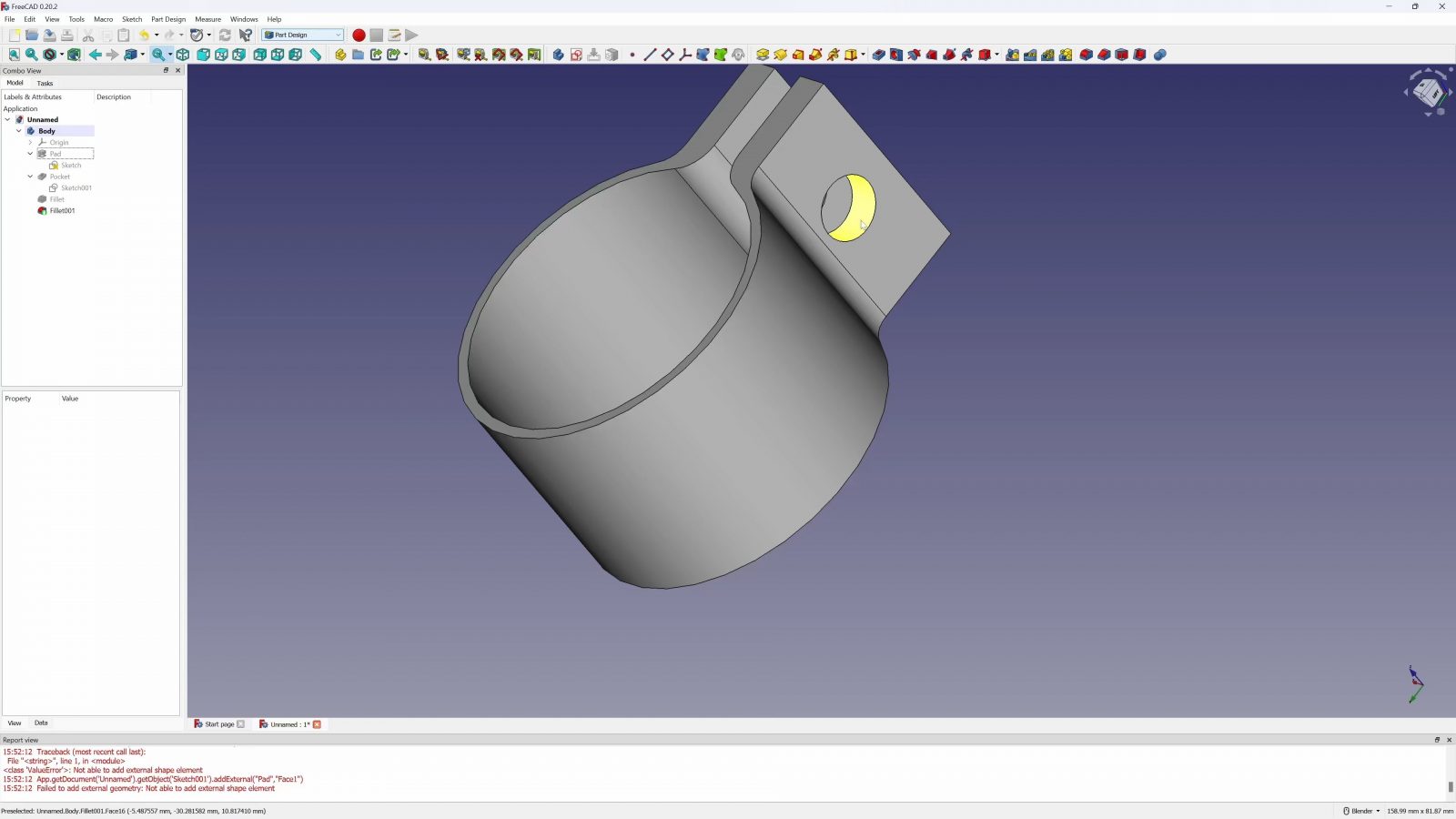
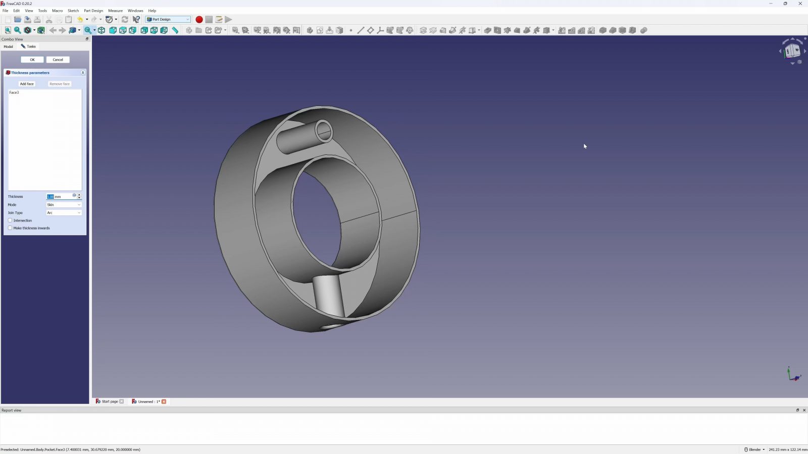
This starts a revolved surface, it gets thickness applied, then it’s split in half, I add the two mating profiles by sweeping along the edge of that cut part, and finally trim them to size. The little retention nub was added later and because I’m using a thickened surface, I can just add that feature to the original surface and it’ll update everything beyond that automatically.
This is all stuff that FreeCAD should be able to do, and at the end of the day, I think the design is actually one of the cleanest parts that I ever built in parametric CAD, so I think it makes for a good candidate for porting between tools.
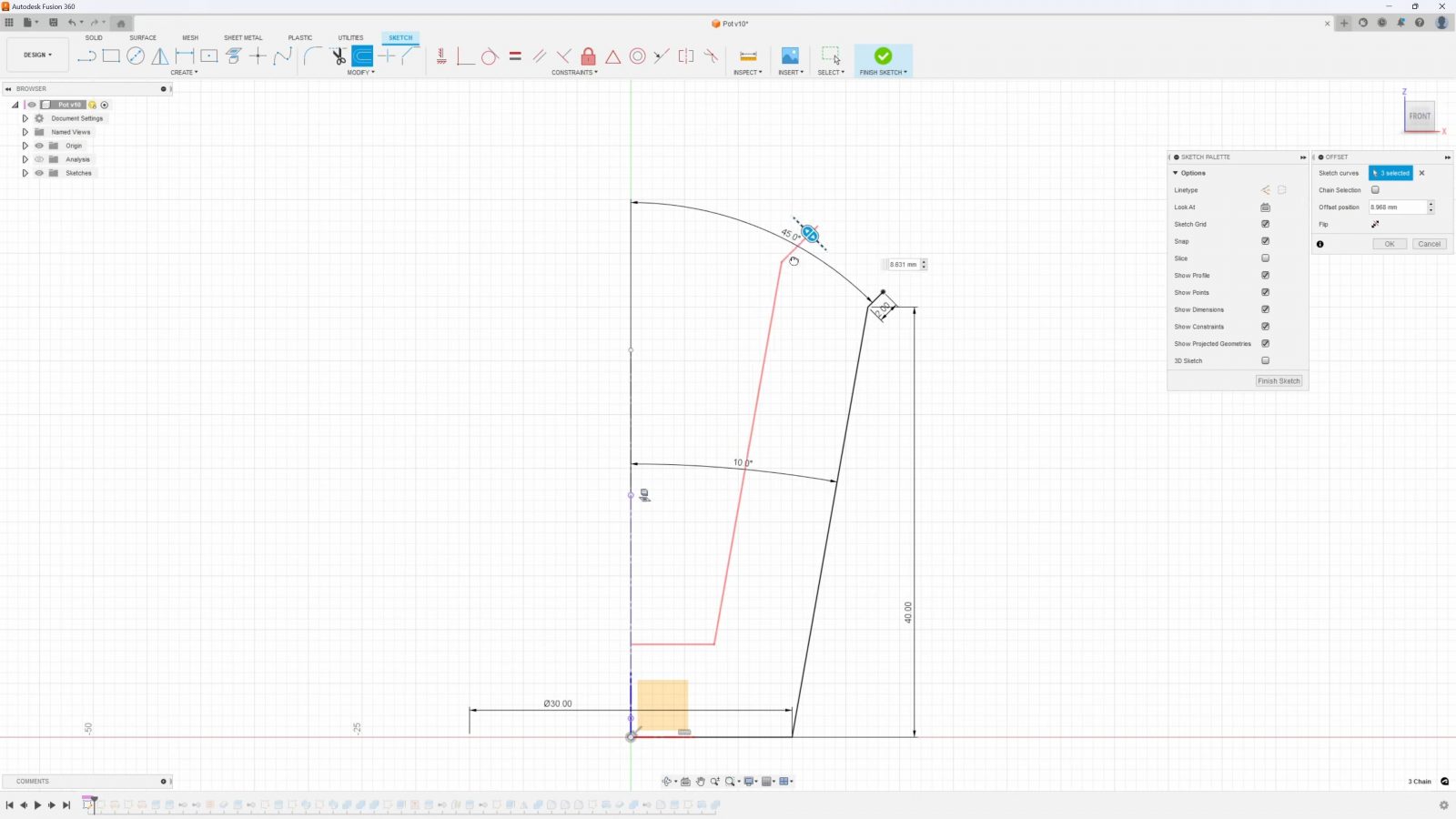
What I think is one of the most important lessons in creating “good” designs in CAD is that you want to avoid redundancies and use the path with the least amount of explicit input from your side. For this part, if you want to create just the basic shell of this pot, instead of sketching out the outer contour, then the inner contour, closing them, then constraining them, and finally creating a revolved solid, the better approach would be to create a sketch offset, because with that, the inner contour is implicitly created by that offset and I only need to specify the offset dimension itself and close the shell, but for the very simplest approach, I just created the three sketch lines for the surface, constrained those, then added thickness to that surface. I’m using what I think is the least complicated and the least explicit way possible of telling the software my intent of “I want this shell shape, with this thickness”.
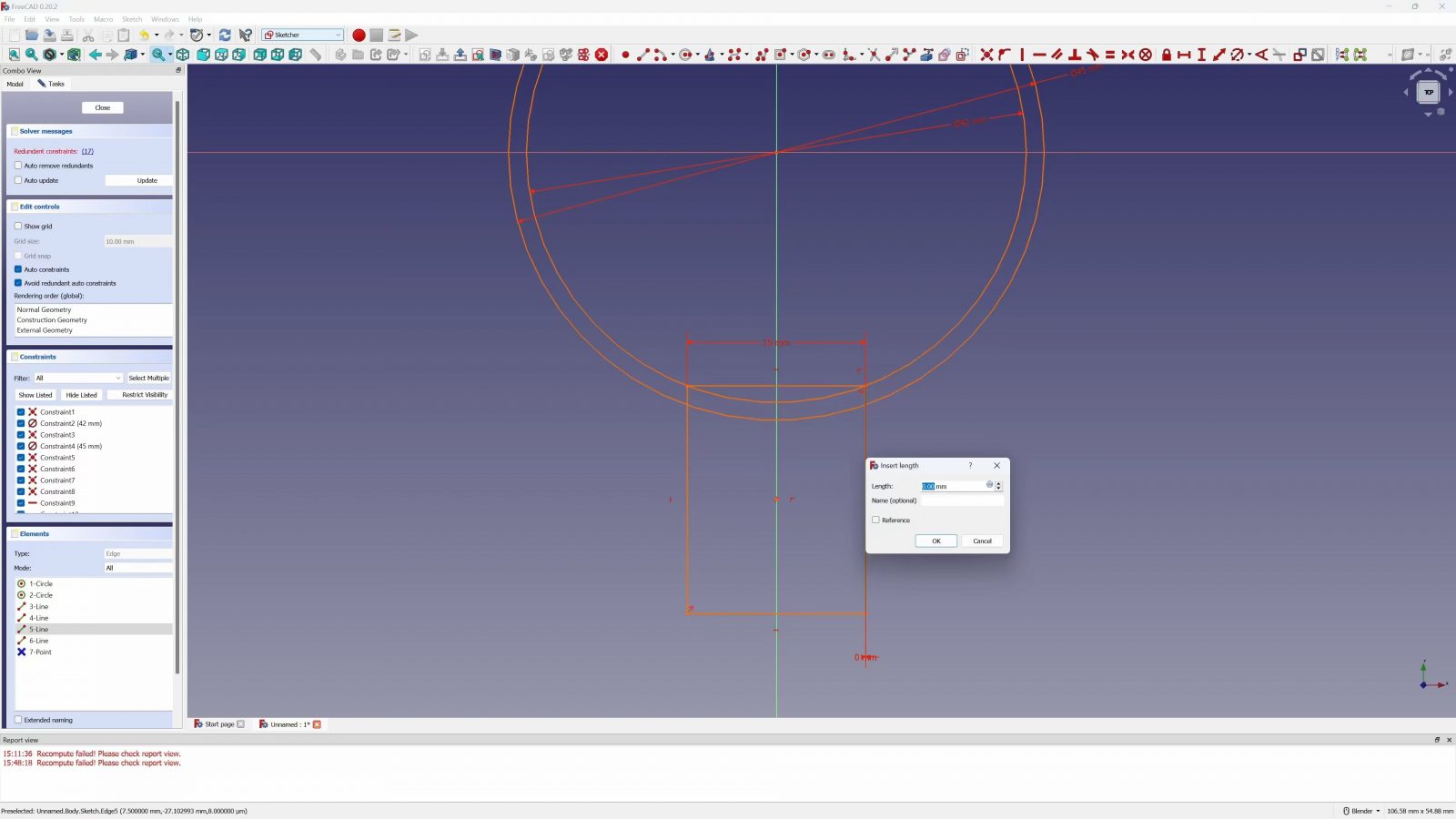
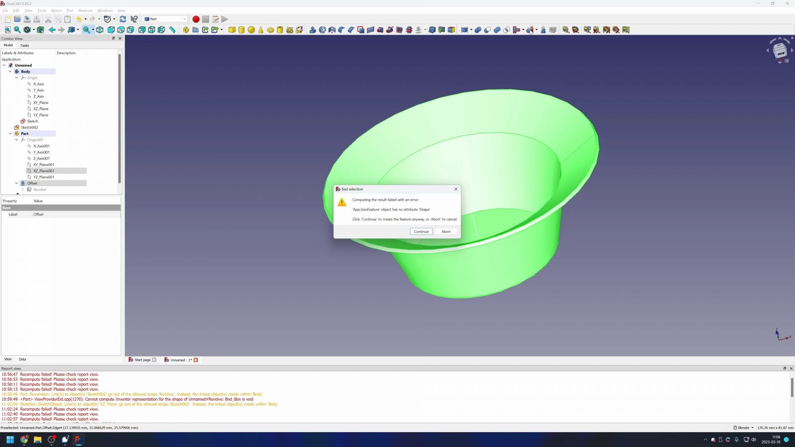
Jumping into FreeCAD with that same approach didn’t go too well. Sure, the fact that I had to google a lot to even find which features I needed to use and whether I should be working in the “Part” or “Part Design” Workbench, that sort of stuff is expected, it’s a new tool, sometimes you just have to read the manual. There’s some official documentation, but lots of info comes from forums and people who are running into the same challenges. I figured out that I could create the “shell from surface” feature by using the surface offset tool, which typically would create just another surface, but when you click the “Fill” checkbox, it actually creates a solid. So far, so good. Next up, I needed to split that part in half, which FreeCAD has several split tools for to choose from. None worked, and the errors that I got had zero helpful google results. So that was a dead end, so I’m thinking maybe I can just not revolve the surface all the way around and have it stop at 180°. Well, now the offset that turns it into a solid stops working.
So back to the full 360° surface, and let’s just cut away half of the part with a new sketch. That works, but it’s about the hackiest solution there is for this. And from what I’ve seen online, and from my own experience, unfortunately, it seems like that sort of solution is what people often gravitate towards when they can’t get the “clean” approach to work.
So, next up, is the profile for the mating surface. Just a couple of lines… and my sketch is overconstrained? I didn’t even manually add any constraints to this, I just dragged a couple of straight lines? So, trying with just a rectangle, it seems like then defining the path to sweep this along is more of a chore than I’m ready for.
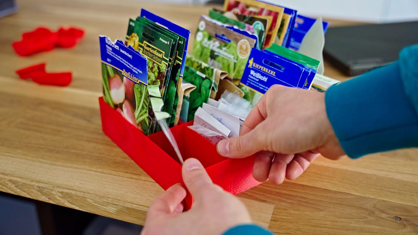
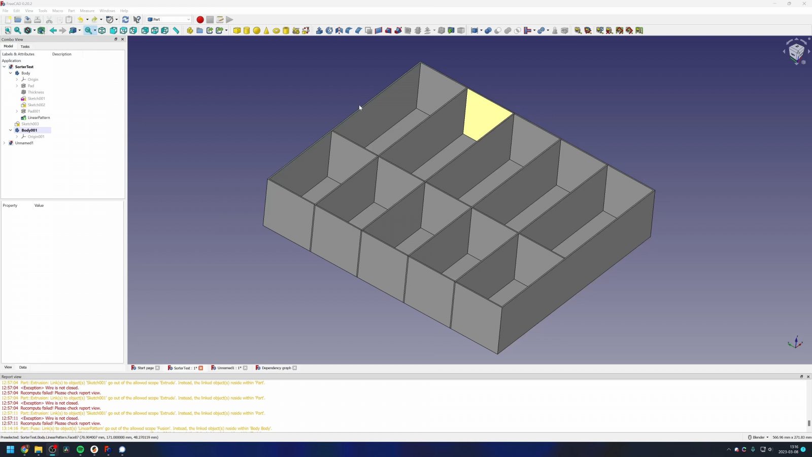
So to have some success, I scrapped this project and tried to make a super simple, all-square sorter box for these little vegetable seed bags, and I did manage to draw and print it, but it took me an hour to figure out how to design something in FreeCAD that I could literally whip up in under 60 seconds in any of the other CAD tools that I know. It’s two boxes, two shell features, a combine and a linear pattern.
By the way, I’ve been referring to Fusion360 as, like, the alternative, this whole time, but it’s just that, under my specific use case, it ever so slightly edges out the alternatives, so it’s the one I’m using mainly. Really, whether it’s Fusion, Solidworks, Onshape, they’re all the same. They all do mostly the same things in the same way. If you can use one, then you’re going to have absolutely no issue using any of the others. Sure, some of the buttons might have different labels, but the principle and the logic behind how you create your parts is the same.
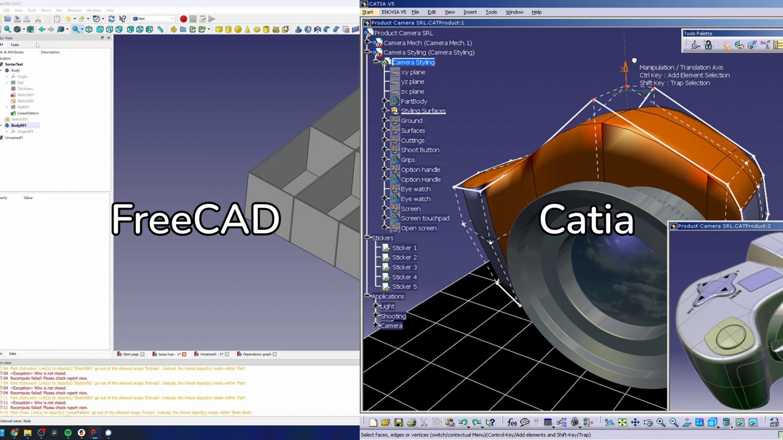
And it almost feels like FreeCAD is close enough to those tools that you might just be able to jump in and learn as you go, but in the end, it’s just different enough that nothing immediately clicks. What it kept reminding me of is Catia v5, a 25-year-old CAD tool that really is only being used by slow-to-adapt and mostly German automakers, as consequence, by their suppliers as well, and it’s generally just a bit less intuitive than the newer CAD solutions out there. I don’t know if the look of FreeCAD is a coincidence, but it does bear an uncanny bit of resemblance to Catia.
For me, FreeCAD has a certain amount of friction to everything you try to do. And I’m not talking about some stuff just not working the way I would expect it to, honestly, that is probably just me not knowing the inner workings of FreeCAD enough to properly use it, but there seems to be a distinct difference in what FreeCAD expects from you vs. Fusion, which is probably the other extreme of the scale. You know the video of the guy who tries to get his kids to write him explicit instructions on how to make a peanut butter jelly sandwich, and then when they don’t include that he should use a butter knife, he just uses his fingers and smears the peanut butter and jelly on there? Well, that’s what other CAD tends to do, and it’s actually a good thing for usability. Using whatever incomplete information you gave it, it’s going to try to solve for it and give you some geometry; it might not quite be what you want at the start, but from there, you can change your inputs and give the tool more information until you have the exact result you want. Going back to the PBJ guy, if he was the FreeCAD equivalent, if you didn’t specify that he should use a knife, he’d just slap you in the face and go “no”.
It’s that difference in approach that I keep seeing in tons of places. Python vs. C++, C++ simply crashes if one of your variables has the wrong type, while Python checks if it has a matching equivalent of the right type and automatically converts it in a lot of cases.
It’s the same implicit vs. explicit approach that I talked about earlier. As a user, I think you really want things to be handled implicitly, but still have the option to override them if the software’s assumptions aren’t actually what you want.
FreeCAD wants almost everything to be given to it explicitly, and you aren’t allowed to screw up giving it that information. It makes the entire process of designing parts what I can only describe as “fragile” – one detail is off, and the entire thing breaks. Maybe the best spot to demonstrate this is when you change earlier geometry in a way that, say, a sketch is missing a reference. What for example Fusion does is that it remembers a “last good” state for that sketch and just leaves it like that and marches on. With a warning. You can ignore and just leave that sketch in a detached, but functional state, or you can go in and fix it and give it new references. But it doesn’t break the entire design and leave you with nothing, which is what FreeCAD would end up doing. And at the end of the day, having a tool that is forgiving in some way, makes for a much less punishing experience using it.
So what would I want FreeCAD to do differently? Obviously, “just make it better” isn’t viable. They’re a really small team, which honestly is probably already way overstating the scale, and aside from a couple of donations and Patreon pages, the developers themselves are donating their time to work on FreeCAD. This means, really, nobody gets to tell them what they should work on and how they should approach things.
I wanted to include OctoPrint sort of as a reference here – another open-source project that you’re probably familiar with, and OctoPrint actually has one full-time developer working on just that project. And even with that, it seems like OctoPrint ends up being a much simpler tool than FreeCAD, but if you look at how Gina spends her time working on OctoPrint, it’s actually not about trying to implement every possible feature under the sun, instead, it’s a lot of polish, debugging, and making sure that the features that are implemented work as expected and in a satisfying way. And for every feature past that, there’s a plugin system.
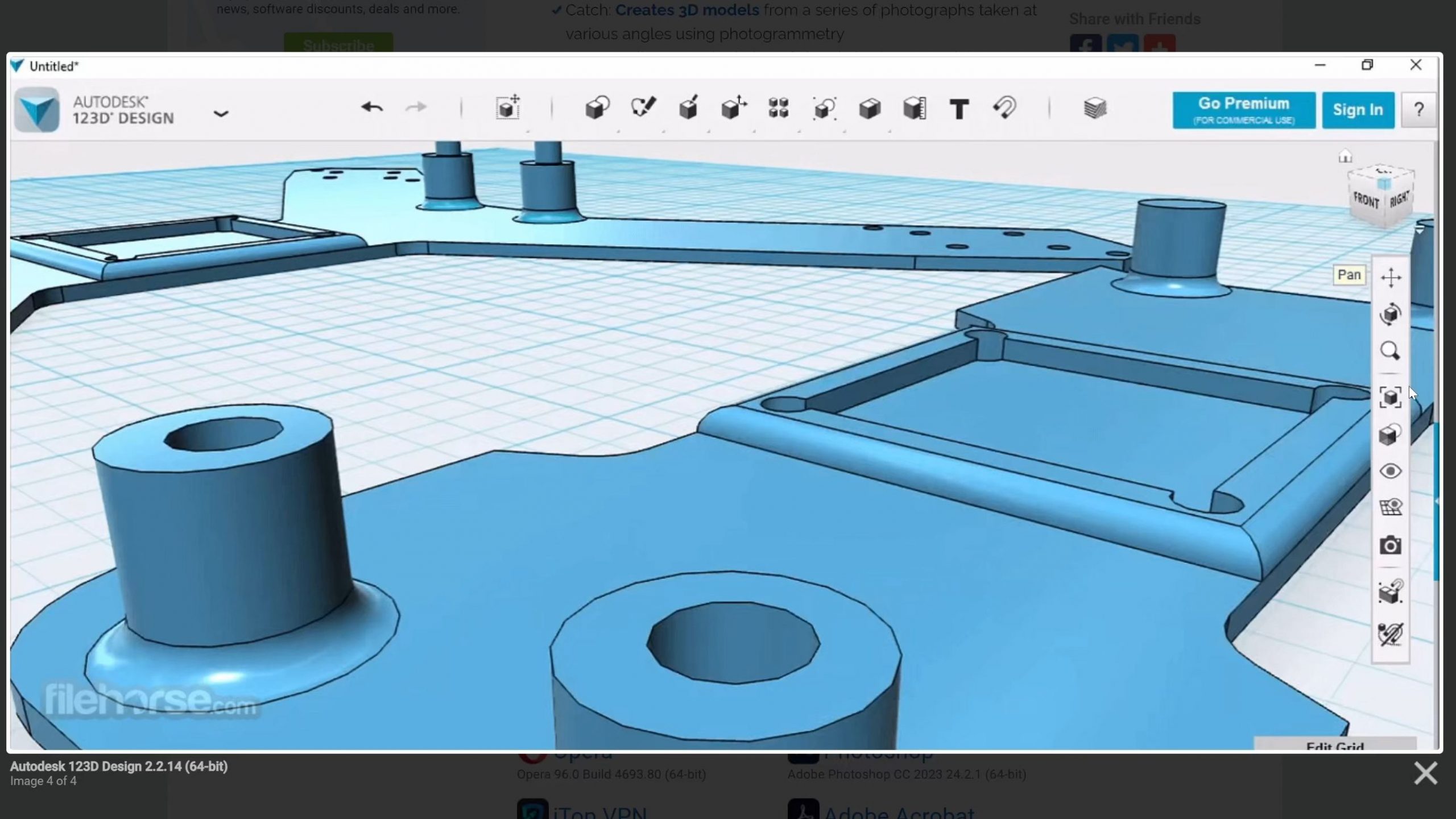
There’s the GNU/Linux mantra of having one tool that does one job, and does that really well. But when I open up FreeCAD and I need a tutorial to tell me which workbench to use to design a basic part, I feel like it’s going a bit in the opposite direction, with it simply trying to do everything. I think a version of FreeCAD that even only focused on super basic CAD and made that really accessible, robust, and straightforward to use, sort of what 123D Design did, that sort of a tool maybe would be of use to a lot more people than the FreeCAD that we have today where, really, you also only do those same basic tasks, but all the other features that, I don’t know how many people actually use, those features also drain from the limited developer time that the project gets.
And again, that’s simply what the devs are choosing to spend their time on, it’s their project, they get to decide what they want to work on, and I get it, implementing a new feature is the much sexier task here. I mean, I’m very much doing that on my own software projects too.
So – should you try out FreeCAD? Sure, it’s free, and maybe it’s going to click for you. It didn’t click for me, but I’ll check back with FreeCAD every now and then and see where things are at. Thankfully, because it’s open source, there are already people creating branches of FreeCAD that are more like how they would envision the tool, and of course, if you’ve got the skills, you can be one of them, but the biggest branch of interest seems to be the one from RealThunder, which focuses on improving some of the underlying architecture and polishing up the user experience. I’ve not tried it, but maybe that would be a better starting point to get into FreeCAD.

Also below the video – the comment section. If you’ve got tips on how to best make use of FreeCAD, let people know, or if you’ve got an alternative tool to check out, I’d be very interested in that as well.
And finally, a shoutout to my Patrons and YouTube members – you all make this entire thing possible, thank you. If you want to find out more, links are on-screen or in the description, thank you for watching, keep on making, and I’ll see you in the next one.
💙 Enjoying the videos? Support my work on Patreon!
Product links are affiliate links – I may earn a commission on qualifying purchases (at no extra cost to you)

Check out my second channel “More Layers” on YouTube for livestreams